
Details regarding computer power supply DC conections, pinouts and their respective voltages.
Author: Neil Patterson ::
2024 Expertek
Views: 6946 - Updated 7/26/2015 10:31 am Print this tip
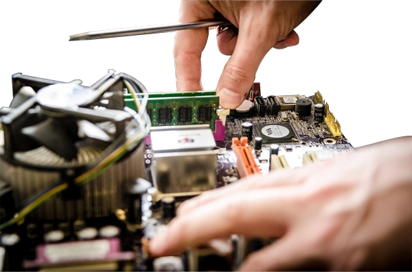
A little something for the geeks in the group, here are some basic diagrams showing connectors and pin-out diagrams for your education and enjoyment. Please note, the AC line cord that connects to the wall carries enough voltage and current to SHOCK and KILL you. Do not open the case of a power supply without taking precautions and knowing what you are doing. The following article does not look at that side of the power supply, merely the DC connections that it provides for mainboard and peripheral power inside the computer chassis.
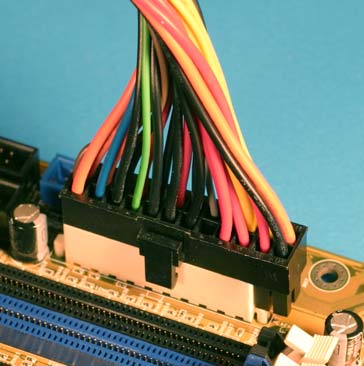
An Installed Main power connector - note that they have left 4 of the 24-pin power cable unconnected (MB didn't have the pins.)
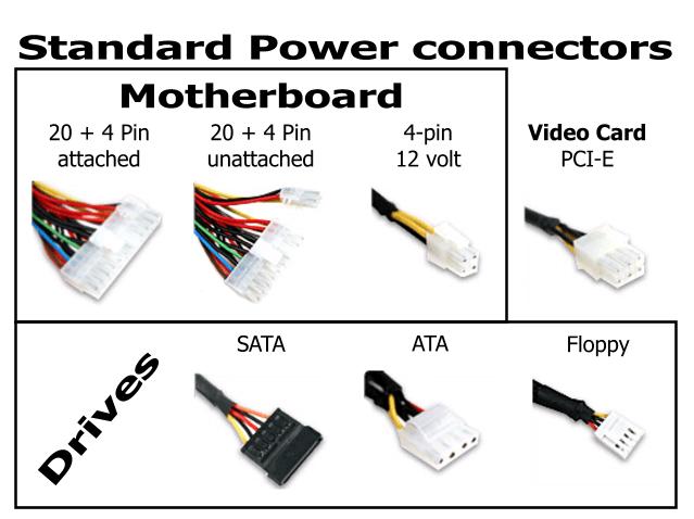
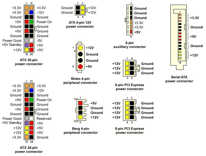
ALL the power connectors.
Here is a diagram of typical pinout configuration of a standard Power Supply. Note that the white cable (pin 18 on the 20-pin connector) opposite the 'power good'(pin 8) is a -5V on the 20-pin connector and reserved on the 24-pin. Generally, you will not see a wire on 24-pin connectors at Pin 20, so a power reading that shows no -5 on the tester is NOT an indicator that the PS is bad. If it is there, and no power reading for -5, it MAY be bad.
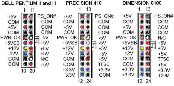
And here is a diagram of the Dell Proprietary pin-outs. Be aware that most Dell power supplies use the diagram above, but certain older Dell models will use the pins shown below with their corresponding Dell models.
Back to the TechTips Index | Hardware Index
Did you enjoy "PC Power Supplies and their connectors and pinouts"??
If you Liked it, SHARE IT!
Ask a question, or Leave a comment below!